- 您现在的位置:买卖IC网 > Sheet目录3896 > PIC16F505T-I/SL (Microchip Technology)IC MCU FLASH 1KX12 14SOIC

PIC12F508/509/16F505
DS41236E-page 18
2009 Microchip Technology Inc.
4.2
Program Memory Organization
For The PIC16F505
The PIC16F505 device has a 11-bit Program Counter
(PC) capable of addressing a 2K x 12 program memory
space.
The 1K x 12 (0000h-03FFh) for the PIC16F505 are
physically
implemented.
Refer
to
Accessing a location above this boundary will cause a
wrap-around within the first 1K x 12 space. The
effective Reset vector is at 0000h (see Figure 4-2).
Location
03FFh
contains
the
internal
oscillator
calibration
value.
This
value
should
never
be
overwritten.
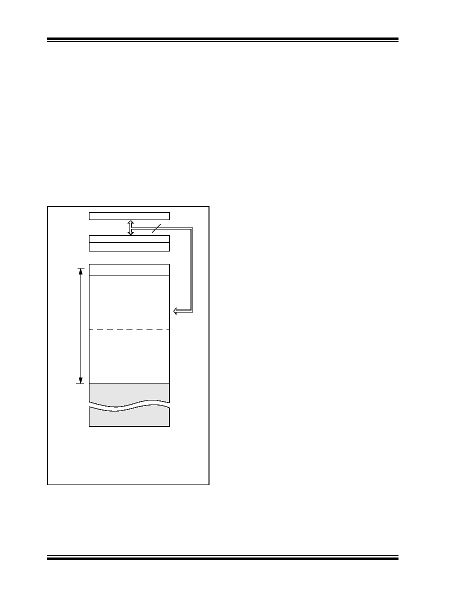
FIGURE 4-2:
PROGRAM MEMORY MAP
AND STACK FOR THE
PIC16F505
4.3
Data Memory Organization
Data memory is composed of registers or bytes of
RAM. Therefore, data memory for a device is specified
by its register file. The register file is divided into two
functional groups: Special Function Registers (SFR)
and General Purpose Registers (GPR).
The Special Function Registers include the TMR0
register, the Program Counter (PCL), the STATUS
register, the I/O registers (ports) and the File Select
Register (FSR). In addition, Special Function Registers
are used to control the I/O port configuration and
prescaler options.
The General Purpose Registers are used for data and
control information under command of the instructions.
For the PIC12F508/509, the register file is composed of
7 Special Function Registers, 9 General Purpose
Registers and 16 or 32 General Purpose Registers
accessed by banking (see Figure 4-3 and Figure 4-4).
For the PIC16F505, the register file is composed of 8
Special Function Registers, 8 General Purpose
Registers and 64 General Purpose Registers accessed
by banking (Figure 4-5).
4.3.1
GENERAL PURPOSE REGISTER
FILE
The General Purpose Register file is accessed, either
directly or indirectly, through the File Select Register
(FSR). See Section 4.9 “Indirect Data Addressing:
CALL, RETLW
PC<11:0>
Stack Level 1
Stack Level 2
U
s
e
rMe
m
o
ry
Sp
a
c
e
12
0000h
7FFh
01FFh
0200h
Reset Vector(1)
Note
1:
Address 0000h becomes the
effective Reset vector. Location
03FFh contains the MOVLW XX
internal oscillator calibration value.
1024 Words
03FFh
0400h
On-chip Program
Memory
发布紧急采购,3分钟左右您将得到回复。
相关PDF资料
PIC12F509T-I/SN
IC MCU FLASH 1KX12 8SOIC
PIC10F200T-E/OT
IC PIC MCU FLASH 256X12 SOT23-6
006200516230000
CONN FFC/FPC 16POS 1MM R/A SMD
006200516230000+
CONN FFC/FPC 16POS 1MM R/A SMD
40FMN-BMT-A-TF
CONN FMN HSNG 40POS SNGL NOR SMD
0781191309
CONN FFC/FPC 30POS .5MM VERT SMD
046214012010800+
CONN FPC VERTICAL 0.5 MM 12POS
006200514230000+
CONN FFC/FPC 14POS 1MM R/A SMD
相关代理商/技术参数
PIC16F505T-I/SL040
制造商:Microchip Technology Inc 功能描述:MCCPIC16F505T-I/SL040 14 PIN 1.5 KB F
PIC16F505T-I/ST
功能描述:8位微控制器 -MCU 2 KB 72 RAM 12 I/O RoHS:否 制造商:Silicon Labs 核心:8051 处理器系列:C8051F39x 数据总线宽度:8 bit 最大时钟频率:50 MHz 程序存储器大小:16 KB 数据 RAM 大小:1 KB 片上 ADC:Yes 工作电源电压:1.8 V to 3.6 V 工作温度范围:- 40 C to + 105 C 封装 / 箱体:QFN-20 安装风格:SMD/SMT
PIC16F506-E/MG
功能描述:8位微控制器 -MCU 1.5KB 67 RAM 12 I/O RoHS:否 制造商:Silicon Labs 核心:8051 处理器系列:C8051F39x 数据总线宽度:8 bit 最大时钟频率:50 MHz 程序存储器大小:16 KB 数据 RAM 大小:1 KB 片上 ADC:Yes 工作电源电压:1.8 V to 3.6 V 工作温度范围:- 40 C to + 105 C 封装 / 箱体:QFN-20 安装风格:SMD/SMT
PIC16F506-E/P
功能描述:8位微控制器 -MCU 1.5KB FL 67 RAM 12I/O Comp Ext Temp RoHS:否 制造商:Silicon Labs 核心:8051 处理器系列:C8051F39x 数据总线宽度:8 bit 最大时钟频率:50 MHz 程序存储器大小:16 KB 数据 RAM 大小:1 KB 片上 ADC:Yes 工作电源电压:1.8 V to 3.6 V 工作温度范围:- 40 C to + 105 C 封装 / 箱体:QFN-20 安装风格:SMD/SMT
PIC16F506-E/SL
功能描述:8位微控制器 -MCU 1.5KB Flsh 67RM 12IO Comp 8B ADC Ext Temp RoHS:否 制造商:Silicon Labs 核心:8051 处理器系列:C8051F39x 数据总线宽度:8 bit 最大时钟频率:50 MHz 程序存储器大小:16 KB 数据 RAM 大小:1 KB 片上 ADC:Yes 工作电源电压:1.8 V to 3.6 V 工作温度范围:- 40 C to + 105 C 封装 / 箱体:QFN-20 安装风格:SMD/SMT
PIC16F506-E/ST
功能描述:8位微控制器 -MCU 1.5 KB Flash 67RAM12 I/O 8bit ADC RoHS:否 制造商:Silicon Labs 核心:8051 处理器系列:C8051F39x 数据总线宽度:8 bit 最大时钟频率:50 MHz 程序存储器大小:16 KB 数据 RAM 大小:1 KB 片上 ADC:Yes 工作电源电压:1.8 V to 3.6 V 工作温度范围:- 40 C to + 105 C 封装 / 箱体:QFN-20 安装风格:SMD/SMT
PIC16F506-I/MG
功能描述:8位微控制器 -MCU 1.5 KB Flash 73 RAM 12 I/O RoHS:否 制造商:Silicon Labs 核心:8051 处理器系列:C8051F39x 数据总线宽度:8 bit 最大时钟频率:50 MHz 程序存储器大小:16 KB 数据 RAM 大小:1 KB 片上 ADC:Yes 工作电源电压:1.8 V to 3.6 V 工作温度范围:- 40 C to + 105 C 封装 / 箱体:QFN-20 安装风格:SMD/SMT
PIC16F506-I/P
功能描述:8位微控制器 -MCU 1.5KB 72 RAM 12 I/O Ind Temp PDIP14 RoHS:否 制造商:Silicon Labs 核心:8051 处理器系列:C8051F39x 数据总线宽度:8 bit 最大时钟频率:50 MHz 程序存储器大小:16 KB 数据 RAM 大小:1 KB 片上 ADC:Yes 工作电源电压:1.8 V to 3.6 V 工作温度范围:- 40 C to + 105 C 封装 / 箱体:QFN-20 安装风格:SMD/SMT